
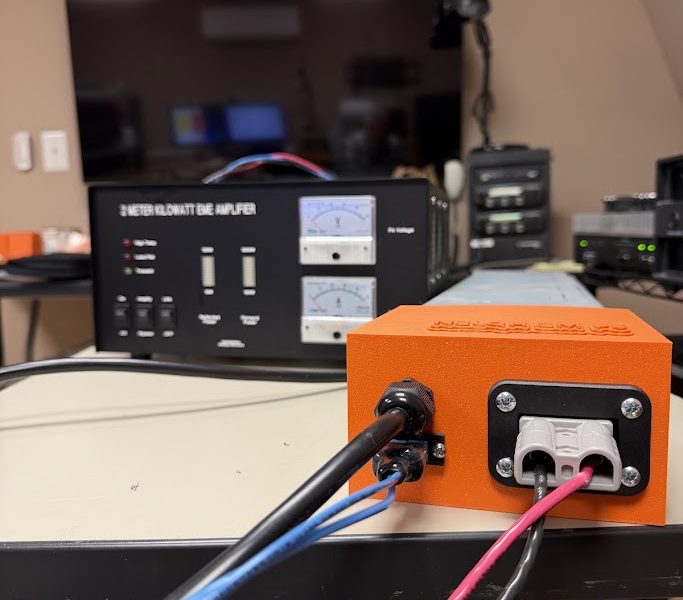
This project uses 240 V AC and about 50 V DC at 30 amps. Either one can kill you, burn you badly or start a fire. If you don’t know exactly what you’re doing, don’t try it. This is a record of my own experimental build. It is not a certified design and it is not safe step-by-step instructions. Check every connection, every bit of protection, the grounding and the cooling for yourself. Electricity doesn’t care how many years you’ve been a ham.
“You Ought to Get on the Moon”
“You ought to get on the moon. Once you do that, you’re going to love it.”
My friend Ray, N3RG, told me that. Ray knows EME. He’s made more than 400 initials, and over 700 contacts if I remember right. Now he’s putting up an even bigger station.
He offered me the gear from his old one. That was two big Directive Systems cross-polarized 2-meter Yagis, the power divider, the crossboom, spreaders, jumpers, an elevation rotator and controller, and a tower-mounted control box with relays and an LNA.
I said sure. The price was right.
Just like that, I was on my way to the moon.
Or so I thought.
Down the Rabbit Hole
What I hadn’t thought through was everything else I’d need. A tower. Two hundred feet of serious hardline between The Lab and that tower. An azimuth rotator. Software. A radio.
And a 2-meter amplifier that could do a kilowatt.
None of it scared me. But the shopping list kept getting longer.
Finding the Heart of the Station
The amplifier came first. Jim Klitzing, W6PQL, builds beautiful VHF and UHF amplifiers. I found a practically new 1 kW 2-meter unit from Jose, N4BAA, who’d decided not to go ahead with his own EME plans. It came with the original box, cables, manual and build sheet. It was already set up for the Icom IC-9700 I planned to use.
The amp also handles sequencing for an external LNA. That matters when you’re trying to hear signals off the moon and then put a kilowatt into the same antennas a second later.
Wait. I Need 50 Volts?
The W6PQL runs on about 50 volts DC. My shack has plenty of power, but all of it is 13.8.
Jim’s paperwork tells you what the amp will draw:
| Output | Current @ 50 V |
|---|---|
| 500 W | 20 A |
| 750 W | 24 A |
| 1,000 W | 29 A |
| 1,200 W | 31 A |
His advice is to set your drive for 29 amps and leave it there, because there’s very little to gain above that.
So I needed 48 to 50 volts at 30-plus amps, with some headroom. EME isn’t SSB. On JT65 or Q65 you transmit for a full minute, then you do it again. It’s a lot closer to a key-down duty cycle than a conversation.
Jose suggested a Mean Well RSP-1500-48. It’s a nice supply, and it runs about $600.
Six hundred dollars. I’d already spent a fair amount on the amplifier. Surely there was another way.
I asked around and found Russ, K2TXB, who’d been running the same W6PQL amp from an HP ESP120 server power supply for years. He had two, and I bought one from him for about $100.
Problem solved.
Until I looked at how it was wired.
The HP ESP120 at a Glance
The ESP120 is an Astec-built module (HPS3KW) that started life in an HP blade-server rack.
- Input: 180–264 VAC, with active power-factor correction
- Output: 48 V at 57 A (3,000 W), adjustable ±5%. Mine measured 51.4 V.
- Standby: 5 V at 5 A, live whenever AC is applied
- Protection: over-current, over-voltage and over-temperature
- Cooling: its own fans, front to back
- Inrush: 100 A peak
That’s nearly double the current the amp will ever ask for. At 29 amps it’s loafing.
The catch is that it was never meant to sit on a bench. It slides into a backplane and connects through a card-edge connector with four big power blades and a block of 20 small signal pins. Until the backplane tells it to, it won’t put out a single volt.
What Russ Built
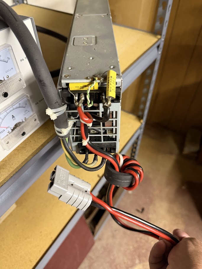
Russ soldered his heavy DC leads straight onto the power blades. Two film capacitors run from the DC legs toward the chassis, and a twisted pair goes to the signal pins. The DC output winds through a big ferrite toroid and ends in an Anderson connector.
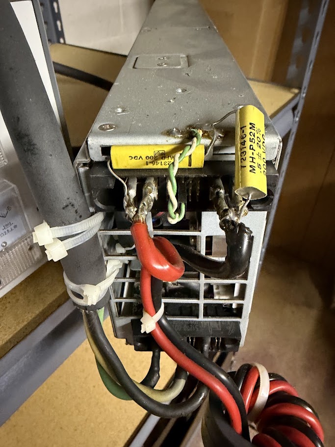
It worked fine, and it had worked fine for years.
But it wasn’t how I wanted mine. There was a lot of exposed metal at 50 volts and 30 amps, sitting under a desk. My control scheme was also going to be different.
I’m not an electrician. I wanted something enclosed, and something that plugged together.
So I started researching. I fed the connector pinout, the datasheet and the amp manual to AI to work out the control pins and what Russ’s ferrite and capacitors were for. The toroid suppresses common-mode RF on the DC leads. The capacitors are extra noise filtering.
I even ordered two Vishay 0.47 µF film capacitors from DigiKey. I haven’t installed them. I’ll wait until the tower, hardline, LNA and IC-9700 are in place and I can hear what the station’s noise floor actually looks like. Any capacitor to chassis has to be rated for that job, and I’ll verify that before it goes in.
How the Supply Wakes Up
Two signal pins matter:
- PSON (power supply on)
- PSKI (power supply kill)
Both have to be pulled to the 5 V standby return before the main 48 V rail comes up. With AC applied and nothing else, the fans run, 5 V sits on the standby pins and the big blades stay dead.
You’ll find two common approaches online.
- Short PSON, PRESENT and PSKI together so the supply comes on whenever AC is present. Then switch the 240 V with a big relay. KE9NS documents it this way, using a DPST relay on the mains.
- What Jim’s manual expects. The amp has two blue wires that come from its front-panel power switch. They’re meant to go in series with the AC line feeding the supply, so the amp’s switch turns the supply’s mains on and off. A 15-ohm power resistor in series limits inrush, and a relay shorts it out once 50 volts appears.
I didn’t love either one. Option 1 means another 240 V relay box. Option 2 means a front-panel switch carrying the mains for a supply with a 100-amp peak inrush spec.
So I went a third way:
- PSON jumpered permanently to standby return
- PSKI wired through the amp’s blue wires
The amp’s front switch turns the 48 V output on and off. The switch carries a few milliamps of 5-volt logic instead of mains current.
Jim W6PQL to the Rescue
Before I committed, I emailed Jim. Were the blue wires really isolated? Would using them for a low-voltage enable upset the amp’s soft-start?
He answered on October 29. The contacts are electrically isolated from the chassis and the DC rails. The 15-ohm resistor is there so the switch doesn’t weld itself shut on AC mains. With the low-voltage approach, it doesn’t matter.
He also said the 51.4 V I’d measured was fine for the LDMOS device, so there was no need to turn the supply down.
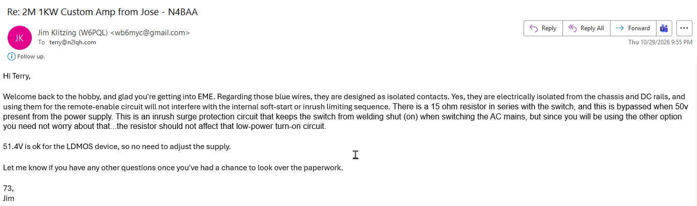
Jim could speak for the amplifier. Finding the right pins on the ESP120 was up to me.
AI helped with the pinout.
It also helped me get it wrong.
Five Prints Later… Nothing
I’ll get to the printing in a minute. First, the part that matters.
I wired everything up, slid the end cap on, checked that the heavy cables weren’t crowded and applied power.
Nothing. Absolutely nothing.
Fans, yes. Five volts on standby, yes. Forty-eight volts, no.
Out came the voltmeter.
The HP pinout sheet draws the DC connector as if you’re looking at the drawing. On the bench, looking into the mating connector on the back of the supply, everything is rotated 180 degrees. It’s mirrored left to right and flipped top to bottom. We’d been reading the diagram one way while the supply sat the other way, and the 5 V standby return was on the opposite side of the block from where we’d been looking.
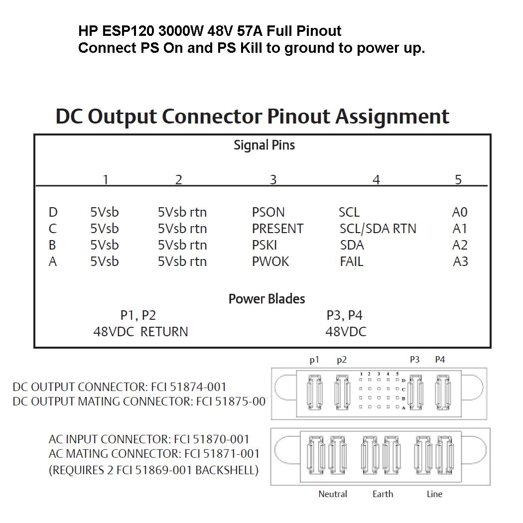
Once I moved the control wires to the right pins, the main rail came alive. Nothing was damaged.
Here’s the part to remember. The same 180° flip that put my control wires on the wrong pins also swaps +48 V and return on the blades. On the drawing, +48 V (P3/P4) is on the right. On my bench, it’s on the left. If you wire the blades from the drawing, you’ll put −48 V into your amplifier.
Trust the meter, not the drawing.
AI is a great research assistant. It’s no substitute for putting a meter on the real hardware.
The Bench-View Map
This is what you actually see looking into the connector on the back of the supply:
| From | To (bench view) | Signal | Notes |
|---|---|---|---|
| Amp RED | Left blades P3 + P4 | +48 VDC | 35 A in-line fuse (still to be installed; see below) |
| Amp BLACK | Right blades P1 + P2 | 48 V return | Use both blades |
| Amp BLUE #1 | 2nd row from top, 3rd column from right | B3 PSKI | Switch closed = 48 V on |
| Amp BLUE #2 | 2nd row from top, 2nd column from right | B2 5Vsb return | No polarity |
| Jumper | Bottom row, 3rd column → 2nd column from right | D3 PSON → D2 | Permanent |
| (nothing) | Rightmost column | 5Vsb | Never short this to ground |
My full wiring reference is in the downloads below.
240 Volts and No Neutral
The AC connector is labeled Line, Earth and Neutral. US 240 V doesn’t have a neutral. It has two hot legs, 120 V each to ground. Data centers run these supplies line-to-line on 208 V all the time, and that’s how mine is fed:
- Line blades: hot leg #1 (black)
- Neutral blades: hot leg #2 (white, marked as a hot)
- Earth blades (middle): green safety ground, and nothing else
Earth is not neutral. If you put a hot leg on Earth, the supply case is live. Before anything else, I put a meter from the case to ground and confirmed 0 VAC.
The cord is 12 AWG SJTW with a Leviton L6-20 locking plug. My shack had only one 240 V outlet, so I added an L6-20 Y splitter. A splitter doesn’t add capacity. Everything on that 20-amp circuit still has to fit, including the supply’s inrush when it starts.
For scale: at a kilowatt out, the amp pulls about 29 A at 50 V. That’s roughly 1,450 W of DC, and about 7 amps from the wall at 240 V.
Building It
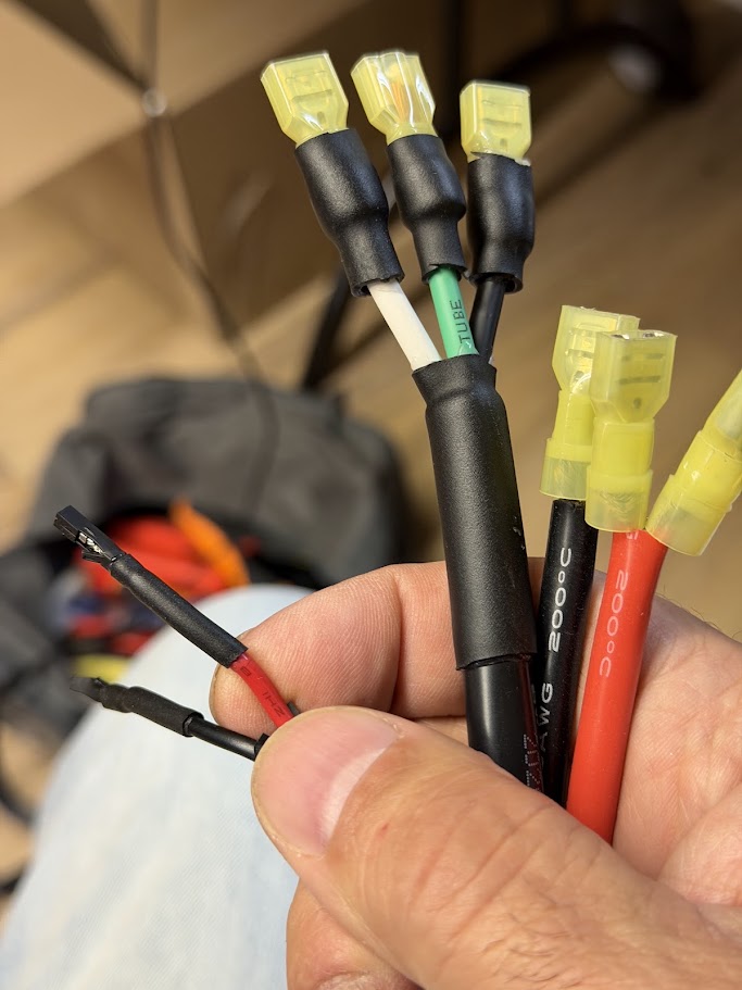
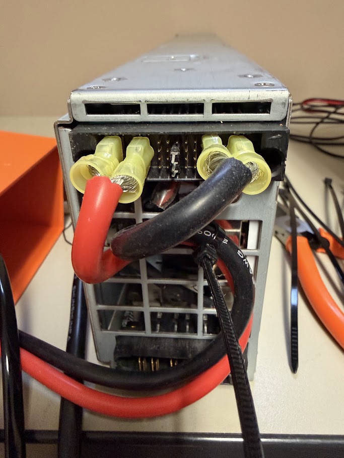
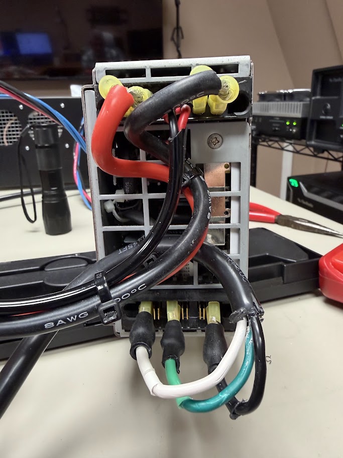
There’s no solder on the blades this time. Everything is crimped:
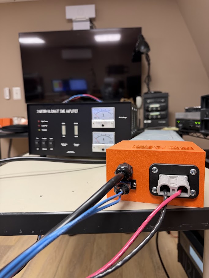
- DC: red and black 8 AWG, 200 °C silicone leads with insulated female spades, two per polarity so both blades share the current. They run to an Anderson SB50 in the end cap, and 8 AWG carries it on to the amp. I’d bought some 6 AWG too, but I ended up using 8 all the way.
- Control: single-pin Dupont-style crimps under heat-shrink for PSKI, the standby return and the PSON jumper.
- AC: insulated spades on the three AC blades, then out through a cable gland.
My First Project on the Snapmaker U1
I’ve run a Snapmaker A350 for years. The new four-toolhead Snapmaker U1 caught my eye. Naturally, my first project on a multicolor machine was a single-color orange box.
I started from a printable enclosure for a similar server supply and adapted it to slide over the ESP120’s rear connector. I added holders for the control wiring and a mount for the SB50.
It took five prints to get the openings and mounting holes right. Even then, I had to file one hole to get a screw through the SB50 mount.
Power-Up Checklist
This is what I do now, in this order:
- AC on, amp switch OFF. The fans run in standby, there’s 5 V between the standby pins (rightmost column to the second column), and there’s 0 V on the blades.
- Amp switch ON, amp NOT connected. You should see about 48–51 V on the blades. With meter red on the left blade and black on the right, it has to read positive. If it reads negative, stop.
- Measure signal pins against the 5 V standby return, not the 48 V blades. The standby ground floats relative to P1/P2 when the main output is off. Use the wrong reference and you’ll chase ghosts.
- The blue-wire path reads about 15 ohms through the amp until its relay pulls in. That’s normal. It’s the inrush resistor.
- If the supply won’t start, pull AC for 30 seconds to clear a protection latch-off and try again.
Time to Make Some RF
With the supply running, I connected my IC-705 to the amp and sent the output into my existing Directive Systems 2-meter weak-signal Yagi.
Naturally, the one cable I couldn’t find was a simple mono 3.5 mm-to-RCA PTT cable. Back to Amazon. It came the next day.
I started at about a watt of drive and watched the meters. I brought the drive up slowly and ended at about 500 watts out, with no reflected power showing. That’s around 20 amps from the supply, or roughly a third of what it’s rated for.
The IC-705 did its job, the W6PQL made RF, and a $100 server supply powered it.
It’s not a full-kilowatt endurance test. But it’s a pretty encouraging first result.
Oh, That’s Warm
Then I touched the end cap.
Warm.
That’s when it hit me. I’d put my beautiful printed box over the exhaust end of a server power supply. Those fans push air out the back, right where I’d capped it.
So much for the beautiful design. Out came the step drill. I put two vent holes in each side and one in the end. After another hour or so of testing, the temperature seemed much more reasonable.
If I print it again, the vents will be in the model. Will I reprint this one? Probably not. It’s going to live under the desk in what has become a pretty impressive rat’s nest of cables. Before I call the cooling done, though, I’ll check temperatures under a long, high-duty-cycle load.
What Actually Matters
- Headroom. A 57-amp supply feeding a 29-amp load lives a long, boring life. EME means minute-long transmit periods, back to back.
- Low-voltage control. Let the amp’s front switch carry milliamps of logic, not mains current.
- Orientation. Every other mistake in this project cost me time. Getting the blades backwards would have cost me an amplifier.
- Airflow. A server supply expects a rack’s worth of airflow. Don’t block the exhaust, and don’t print a box that does.
- Crimp, enclose, and connect. You should be able to unplug it without touching a blade.
What I’d Do Differently
- Map the connector with a meter before I wire anything. Find the 5 V standby pin, mark it on the case, and work from there.
- Put vents in the model before the first print, not after the fifth.
- Install the fuse first. The amp’s manual calls for a 35 A in-line fuse on the positive lead, and it belongs in before RF, not after.
- Print the orientation on the cap. A small “+48 ← | → RTN” on the end cap means the next person doesn’t have to work it out again, and neither do I.
What’s Still on the List
The supply works, but I’m not calling it finished.
- DC overcurrent protection. Jim calls for a 35 A in-line fuse. I also bought a 30 A resettable breaker, and I need to confirm it’s suitable at 50 V DC before I use it.
- RF filtering. The ferrite and the film capacitors will go in once the real EME system is running and I can measure whether they help.
- AC control. The amp switches the 48 V output, but the ESP120’s fans and standby run whenever 240 V is present. Eventually I may add a properly rated, enclosed AC switch under station-controller control, with attention to inrush and cooling.
Downloads
↓ My HP ESP120 to W6PQL 1 kW amplifier wiring reference (PDF)
↓ HP/Astec HPS3KW power supply datasheet (PDF)
↓ W6PQL custom 1 kW 2-meter amplifier documentation (PDF)
These files document an experimental installation and the manufacturers’ information. My wiring reference hasn’t been independently reviewed for electrical safety. Note that it shows a 35 A fuse that is not yet installed.
Parts and Materials
- Snapmaker U1 3D printer
- Anderson SB50 plug quick-connect kit
- Anderson SB50 connector with wire and mount
- HKS female spade connector assortment
- Dupont connector kit
- 38-piece NPT cable gland kit
- 12 AWG three-conductor SJTW cable, 10 ft
- Leviton 2321 L6-20P locking plug
- NEMA L6-20 Y splitter, 3 ft
- FT240-31 compatible ferrite toroid
- 30 A resettable circuit breaker (not yet installed)
Also used: a surplus HP ESP120 (about $100, from Russ K2TXB), and two Vishay Roederstein MKP1839447404 0.47 µF capacitors from DigiKey (bought, not installed). I’ll add links for the PTT cable and the printable model when they’re available.
So, Am I on the Moon Yet?
Not quite.
But I have the amplifier, a working power supply, and a clean first RF test at 500 watts. Next come the tower, the 200-plus feet of hardline, Ray’s crossed Yagis, the control box, the LNA and the IC-9700.
Ray started all this with one sentence. “You ought to get on the moon.”
A couple of antennas later, I’m reverse-engineering server supplies and drilling holes in my first U1 print.
Trust the meter, not the drawing.
The hobby never gets old.
73 de N2LQH · Terry Rossi · South Jersey