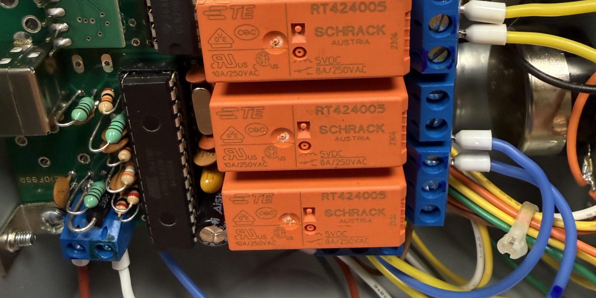
There’s a special kind of pain reserved for realizing you soldered an IC socket on the wrong side of a board. I found that out with a pair of nippers in one hand and a look of pure regret on my face, tearing apart a brand-new relay board because I’d trusted the wrong side of a bare PCB to tell me which way was up.
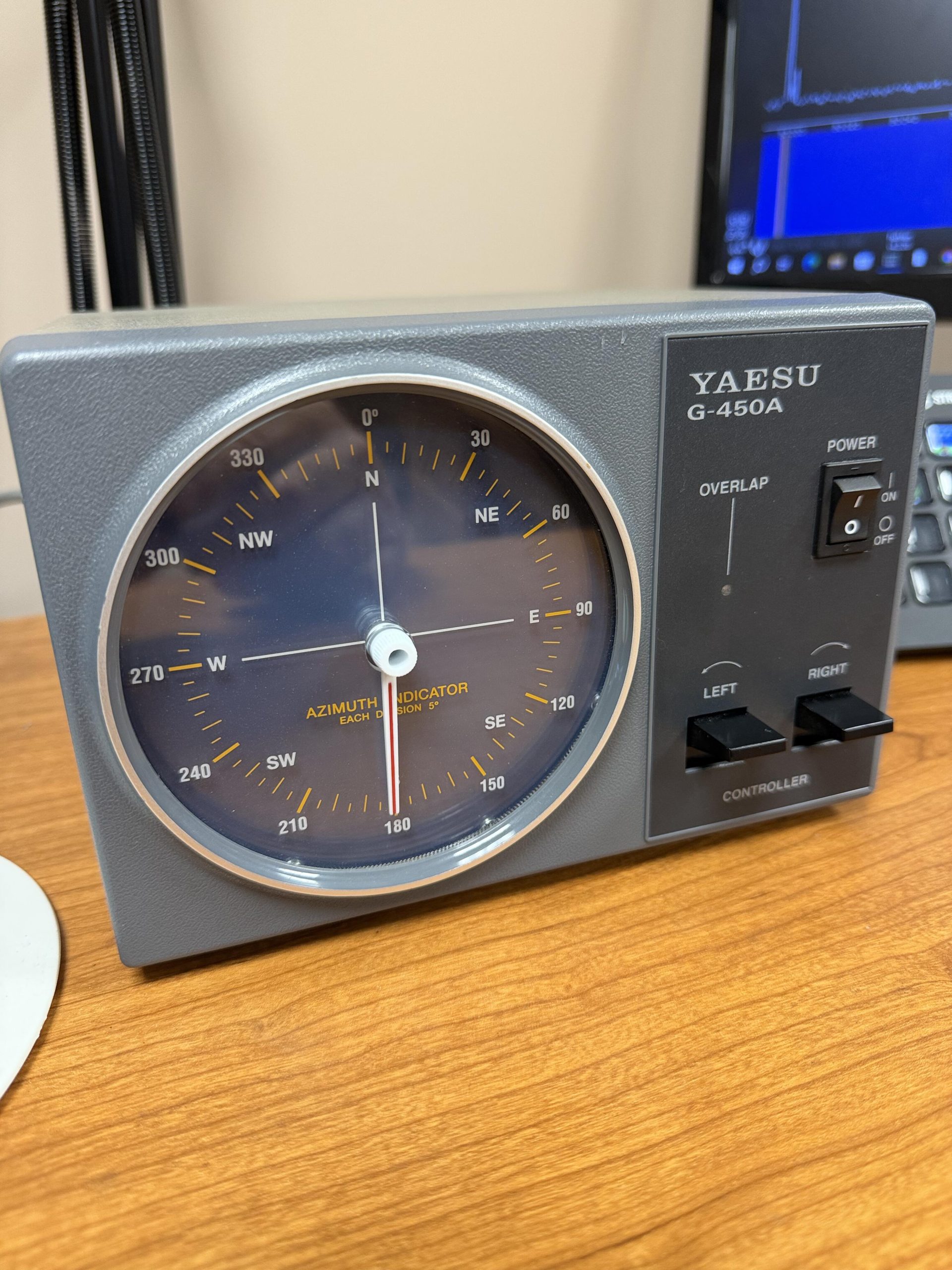
This is the story of how my Yaesu G-450A rotator controller — the one swinging my VHF, UHF, and microwave antennas on the “COW” (Cal Cell On Wheels) tower next to the shack — went from a rotator I had to stand in front of, to one I can point from anywhere I’ve got a connection. The COW itself is a project worth its own writeup, and I’ll get to that one separately. For now, just know it’s a portable, wheeled tower platform doing a very solid job holding VHF/UHF/microwave antennas steady next to the house.
I operate remotely a lot. That’s the whole reason this project existed. A rotator you can only turn by standing in front of a box with a compass dial on it doesn’t do you much good when you’re not standing in front of it. The G-450A is a solid old workhorse, but Yaesu never built it to talk to a computer — so if I wanted to swing that VHF/UHF/microwave array from the road, or from the other side of the house, it needed a brain it didn’t come with.
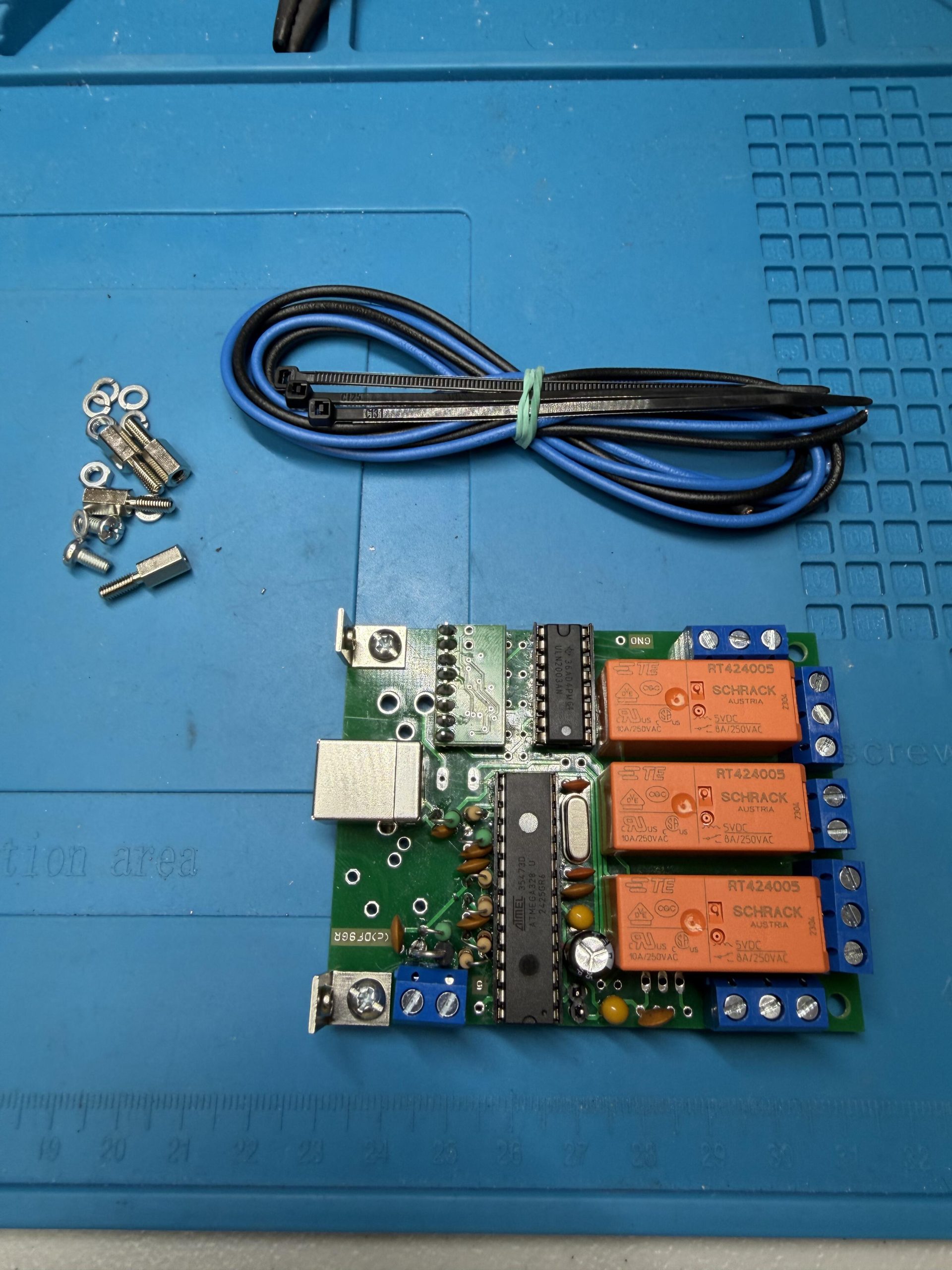
The answer was Schmidt-Alba’s ERC — Easy Rotor Control — Version 4 USB Kit, 85 EUR plus VAT and shipping from Germany (there’s a US distributor through Vibroplex if you’d rather not deal with international shipping). It’s a small board built around an ATmega328, three relays, and a USB interface, designed to drop into a rotator controller and give it a COM port. Simple concept. Not always a simple build.
The kit fights back
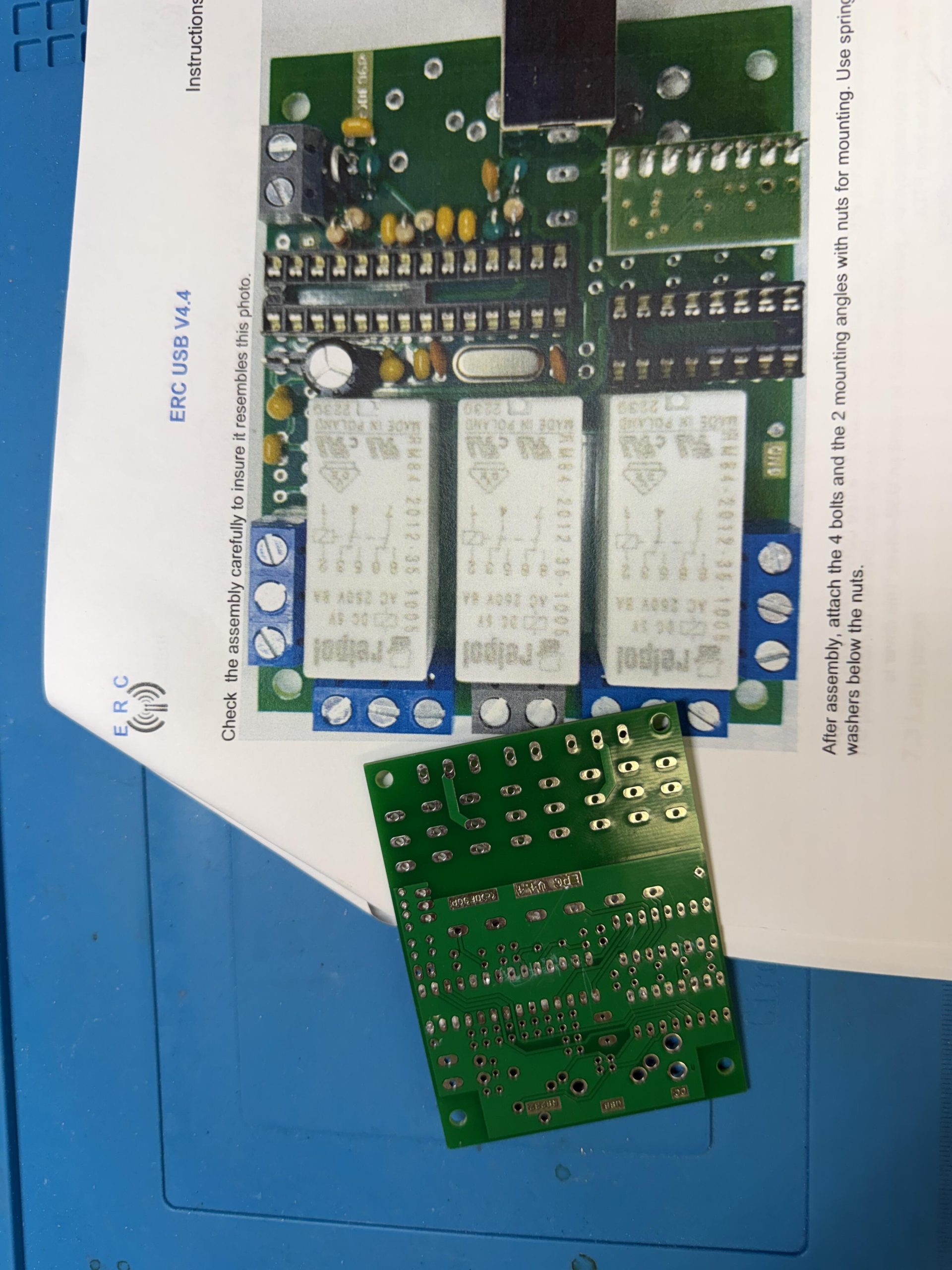
The ERC board is a multi-use design — the same PCB supports several different versions of the controller, which means the parts and jumpering depend on which version you’re building. Smart way to manufacture a board. Not the easiest thing to hand a first-timer with a bare PCB and no silkscreen printing to speak of.
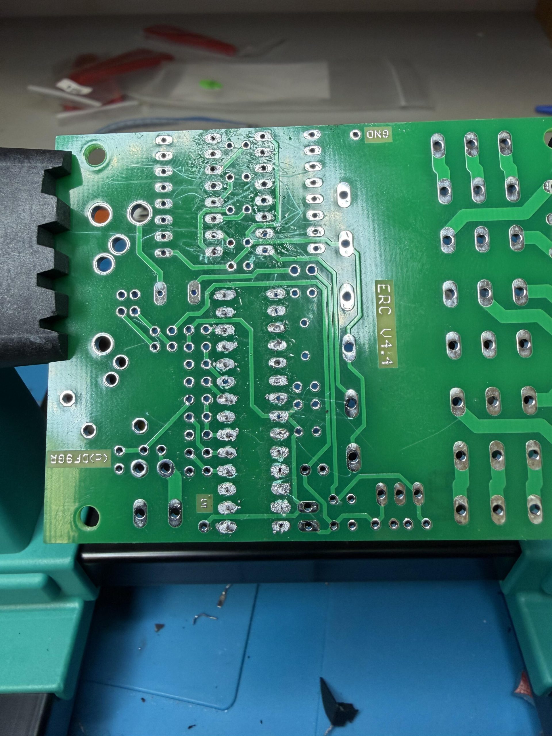
Here’s where it got me: I assumed the side of the board with the most printing on it had to be the front. It wasn’t. It was the back. I built two IC sockets in on the wrong side before I caught it — and if you’ve never desoldered an IC socket, count yourself lucky. It’s exactly as miserable as it sounds. I ended up cutting the sockets apart with nippers just to get them off in pieces, then clearing each hole of old solder before a fresh set — ordered off Amazon — could go in properly.
Lesson for anyone building this kit: don’t trust the printed side to mean “front.” Cross-check against the schematic before you solder anything.
A trip to the club, on a deadline
Once the board was populated, I brought it to the Gloucester County Amateur Radio Club and asked my electronics Elmer, Chris, AD2CS, to look it over. I wanted a second set of eyes before I trusted this board inside my rotator — especially since the weekend I’d built it happened to be the CQ July VHF contest, and I wasn’t about to find out about a bad joint mid-contest. Good thing I asked. Chris found a few cold solder joints my novice hands had left behind. Fixed those, and I plugged the board into my PC over USB.
A new COM port appeared.
Small thing to see on a screen. First real proof the board was alive.
The fit and finish, and a date with a Dremel tool
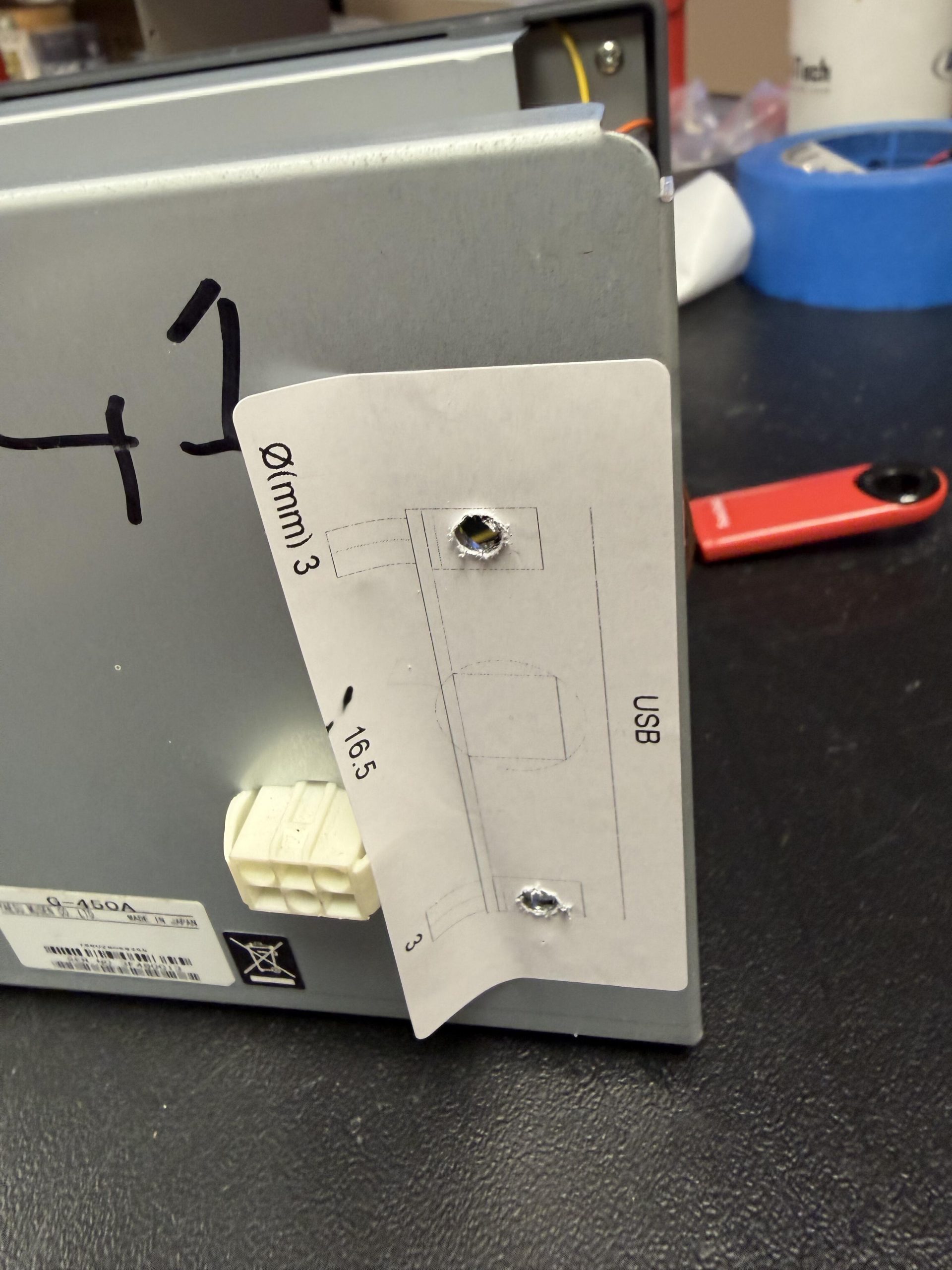
Getting the board back into the G-450A case took a second try. My first placement put it too close to the center of the case, and the back edge collided with the top shelf plate — the one holding several of the rotator’s internal connectors. Nothing fit until I moved the board closer to the edge, and even then, I needed to carve out two or three centimeters of that upper plate with a Dremel for clearance. Once that was done, the board sat right, the case buttoned back up clean, and the rotator’s feet went back on.
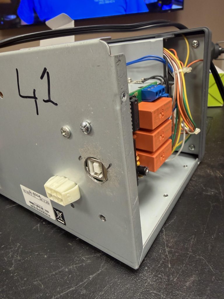
A quick aside on that “41” scrawled on the back panel: I picked this rotator up used at the Dayton Hamvention in 2026, and the story that came with it is that it once served at WRTC2014 — the World Radiosport Team Championship held that July in New England, with 59 teams representing 29 regions and 38 countries. I know a couple of hams who were there. I can’t swear “41” was its actual station number and not just someone’s inventory mark, but I like knowing this old G-450A might’ve had a bigger stage before it ended up pointing microwave antennas in my backyard.
Calibration: round one didn’t work
With everything reassembled and plugged back in, it was time to calibrate. The ERC’s basic routine has you drive the rotator to its full counterclockwise and full clockwise limits and sets its reference points from there.
It didn’t work. The compass headings the software reported didn’t match where the rotator actually was.
The fix was the ERC’s extended calibration — it steps the rotator every thirty degrees around the full rotation and fine-tunes the calibration point by point, instead of relying on just the two endpoints. Once I ran that, it locked in and tracked perfectly.
The software side was almost a letdown
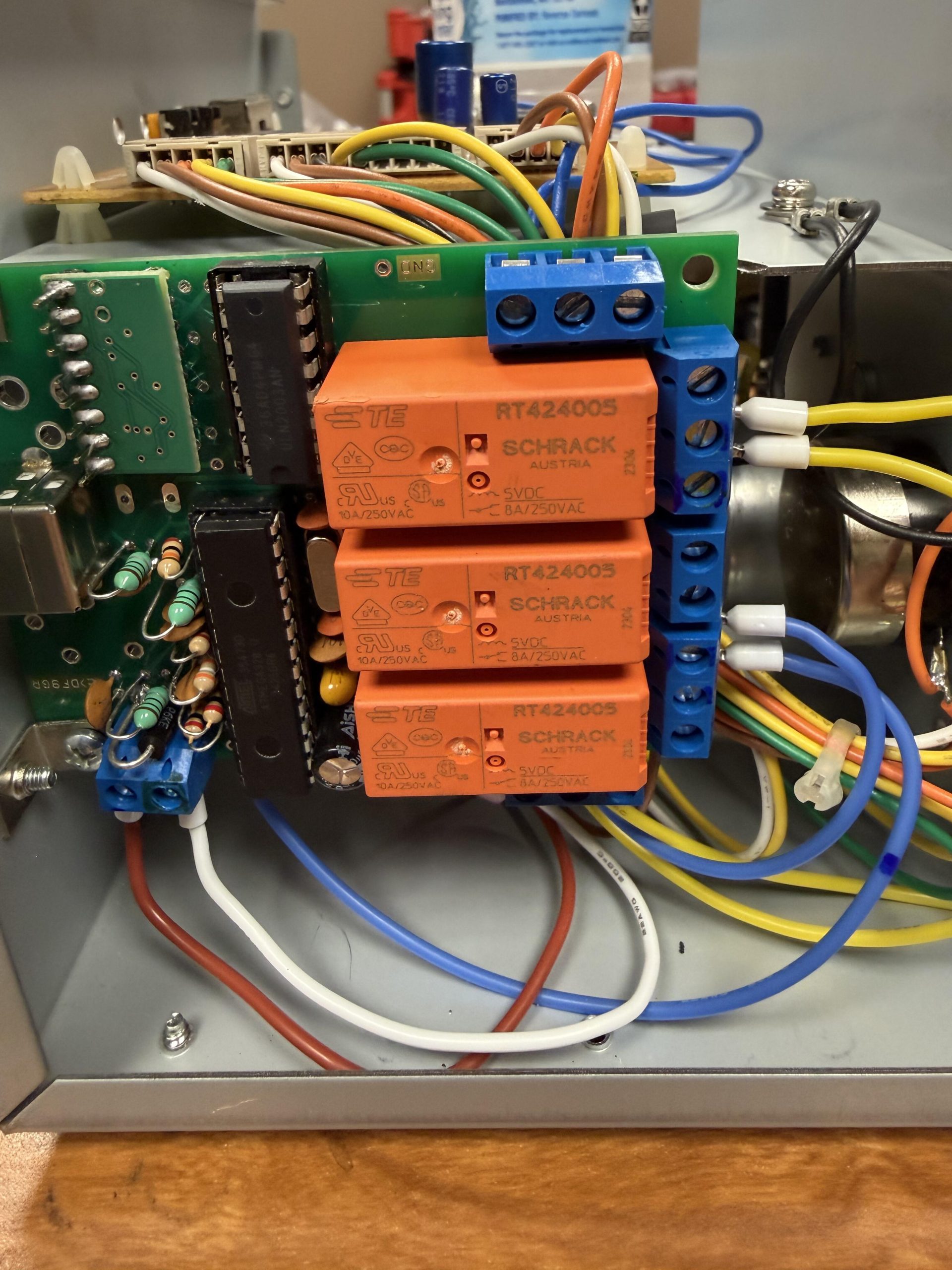
After the soldering fight, the Dremel work, and two rounds of calibration, I expected the software integration to be its own ordeal. It wasn’t. My rotator control hub is PstRotatorAZ, and hooking up the ERC board was about as simple as software gets: set the controller type to ERC, pick the COM port, done. From there, PstRotatorAZ bridges straight into both Ham Radio Deluxe, my logging program, and N1MM Logger+ for contesting — so however I’m operating, the rotator just follows along.
Where it stands
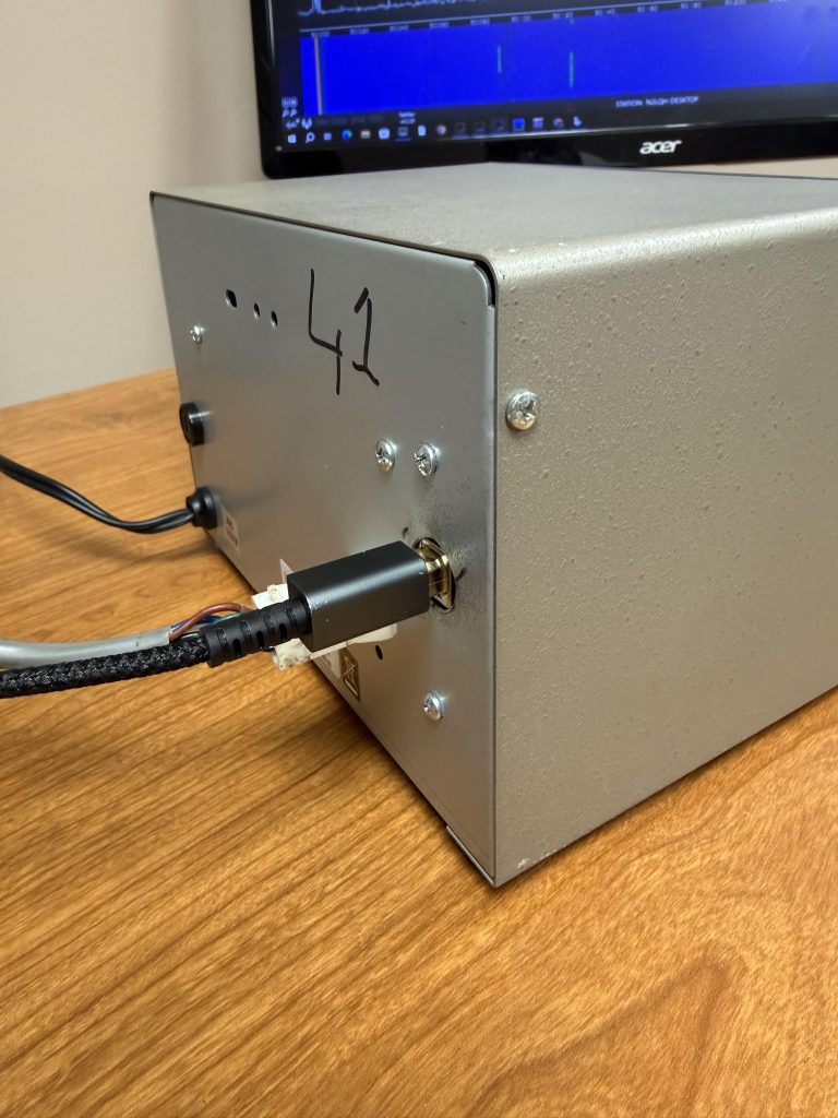
The rotator’s back on the tower, fully live, and working through both logging applications and PstRotatorAZ. It’s a small box with three relays and a USB port, but it’s going to make a real difference — I’ll be able to remotely swing that transverter-and-Flex combination covering VHF, UHF, and microwave from wherever I happen to be operating.
Not a bad return on one afternoon of desoldering regret.
73 de N2LQH · Terry Rossi · South Jersey